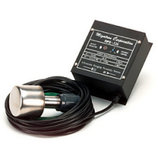
RPS-8000 Controller With Remote Sensing Heads
Ranges: 4-12″, 5-36″, 8-72″
Mdivtiplexed: 2-8 transducers
Narrow beams sensor
On/off output
Product Description
- Various Sensing Ranges
- Narrow Sensing Beam
- High Frequency
- LED Indicator
- Sealed Transducer
- Multiplexed 2 – 8 Tranducers
- Analog Current and Voltage
- Isolate Form C Relay Outputs
- Temperature Compensation
- Small Remote Transducer
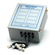
The RPS-8000A was designed for applications where 2 or more sensors are needed in a general area. The RPS-8000A can handle up to 8 TSR-3 transducers, and the RPS-8001A up to 8 SSR-3 transducers (stainless steel). These transducers are multiplexed so they can all operate in close proximity with each other without interference. Each sensor has three outputs: an analog voltage, analog current, and form C relay. The Analog outputs each have a zero and span control as well as an inverting switch if a decreasing signal with distance is desired. There is a 25 turn pot provided for each relay output so the detect point can be adjusted.
Another feature is the instrument’s ability to compensate for temperature changes. To accomplish this sensor “0” looks at a fixed distance and adjusts the circuit to give a proper reading. Since all the other channels use this same compensated circuit they, too, become compensated for temperature, humidity, and pressure changes. The RPS-8000A also has the ability to be controlled from an external source. When operated in this mode the user can direct any of the 8 sensors to output “S1”. This then requires the need for only a single input. Another external control is the RATE. This controls the rate at which the sensors will update.
[Download not found]Transducers
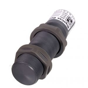
The RPS-8000A uses the TSR-3 transducer. The transducer heads are made of Delrin with epoxy face for the 14″ and 36″ sensors and Valox with a silicon face for the 72″. The RPS-8001A uses the SSR-3 transducer. This is a sealed sensor with a 303 stainless steel threaded housing and a 302 stainless steel sensing face. Both types of transducers have a narrow sensing beam.
OUTPUTS
The RPS-8000A has three different outputs per sensor. Any one or all of the outputs may be used at the same time. The relay output is a form C containing a N.O. and N.C. contact. It is rated for a .5 Amp. at 120VAC. The analog voltage output is 2 – 10 volts. It’s load must be 5K or greater. The analog current output is 4 – 20mA. It’s load must be 300 ohms or less. These analog outputs can be scaled to occur over a variety of ranges.
ZERO & SPAN CONTROLS
The RPS-8000A comes with zero and span controls for each sensor. These two potentiometers allow the analog signal to be adjusted over a desired range. The adjustment ratio is 5 : 1. This means that with the 4″ to 12″ range the analog output can be adjusted to give an output over a range as small as 1.6″ or as large as 8″. Example: If you desire a 2v signal at 5″ and a 10v signal at 10″ you would adjust the following way: 1. Turn the span (gain) control fully cw. 2. Adjust the zero (bias) control for 2v with a target 5″ away. 3. Place target at 10″ and check the voltage. It should read higher then 10v so turn the span control a half turn CCW. 4. Adjust the zero control for 2v with the target 5″ away. Recheck the reading at 10″. If it is still high turn the span control CCW a half turn again and continue repeating these steps until the desired range is reached. ( NOTE: When adjusting the span control do not try to tune in the desired voltage or current. This must be achieved by adjusting the zero control and then checking the far range. )
Inverting Analog Signals
Both the analog current and voltage outputs of the RPS-8000A can be inverted. In the non-inverted state the analog output increases with distance. In the inverted state the analog output decreases with distance. This inverting option is selected by activating a switch on the channel in which this output is desired.
Temperature Compensation
Sensor “S0” is used to compensate all the other sensors when used in the temperature compensation mode. When not used in this mode it becomes another sensor and all the sensors become uncompensated. To accomplish this feature sensor “0” looks at a target at a fixed distance either 6″ or 12″ away. The circuit then adjusts to give a proper reading. Since all the other channels use this same compensated circuit they become compensated for temperature, humidity, and pressure changes. The final option is averaging the compensated signal. This may be desirable if there are air currents with a wide range of temperature variations in them.
External Controls
There are 7 input lines and 1 output line which can be used to control the RPS-8000A if desired. There is a 3 bit access word which will address any sensor. All sensors can be multiplexed to Sensor 1 output. In this condition any sensor addressed will have its output appear at Sensor 1 output.
An open collector output marked “Flag” can determine when the data at the output addressed is valid. Each time the address is changed the FLAG will go high and remain there until the system has turned on. Update time is also user selectable from 6,9,7,12 ms. between sensors for the 12″ range.
Proximity Detection
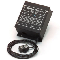
Proximity detection is the detection of an object in a given range. The detection range of the RPS-2325 is controlled by the “Range Control” potentiometer located on the front cover of the controller. Any object within the desired range is detected, while objects out of range are ignored. The detect point is independent of size, material, and reflectivity. The Proximity Option is denoted byt the part number RPS-2325-14.
Ranging Measurement
With the RPS-8000A analog outputs of 2-10 VDC and 4-20 mA are provided. Precise distances of an object moving to and from the transducer are measured via time intervals between transmitted and reflected bursts of ultrasonic sound. The example shows a target detected at 6 inches from the transducer and moving to 10 inches. The distance change is continuously calculated and outputted.
| Specifications: | |
| Operational Range: | Adjustable 4″ to 12″ Adjustable 5″ to 36″ Adjustable 8″ to 72″ |
| Power Input: 120VAC | 120VAC 15-24 VDC |
| Input Current: | 75mA max. AC 600mA max. DC |
| Ambient Temperature: | 5ºC to 49ºC or 40ºF to 120ºF |
| Humidity: | 0% to 95% Non-condensing |
| Enclosure: | Metal Nema 12 TSR-3 Galvanized Steel Housing |
| Controller: | Silicone Rubber Sensing Face, Epoxy Filled SSR-3 303 Stainless Steel Housing |
| Transducers: | 302 Stainless Steel Sensing Face, Epoxy Filled |
| Outputs: | Isolated Form C Relay .5 Amp Max. at 120 VAC |
| Output (2) N.O., NC | Isolated Form C Relay .5 Amp Max. at 120 VAC |
| Response Time: | 8″ to 72″ ON 100mS – 2S OFF 100mS – 2S |
| Accuracy: | +- .040″ or +- .3% of range whichever is greater at 40º – 120º F |
| Weight – Controller: | 22lbs |
| Weight – TSR-3: | 4.5 ounces |
| Weight – SSR-3-72: | 5.5 ounces |
Figure:
- Angle of Tilt
- Beam Spread
- Mounting Dimensions for Controller
- Mounting Dimensions for Transducers
| PART NUMBER | RANGE | OUTPUT |
| RPS-8000A-12 RPS-8000A-36 TSR-3 RPS-8000A-72 TSR-3-72 |
4″ – 12″ 5″ – 36″ 8″ – 72″ |
8 Channel System, Analog outputs, Form C Relays, Temp. Comp. 8 Channel System, Analog outputs, Form C Relays, Temp. Comp. Transducer for RPS-8000A, Galvanized Steel, Silicone Face 8 Channel System, Analog outputs, Form C Relays, Temp. Comp. Transducer for RPS-8000A, Galvanized Steel, Silicone Face |
| RPS-8000-72 SSR-3-72 |
8″ – 72″ | 8 Channel System, Analog outputs, Form C Relays, Temp. Comp. Transducer for RPS-8001A, 303 Stainless, 302 Stainless Face |
